How to Choose the Right Air Breaker for Your Needs?
Choosing the right Air Breaker begins with understanding the equipment it must protect. A workshop motor, apartment panel, and commercial distribution board demand different solutions. Each installation has its own load profile, fault level, space limits, and maintenance needs. A device that works well in a small office may perform poorly beside a high-starting-current pump.
The selection process should examine rated current, voltage, breaking capacity, trip characteristics, pole configuration, and installation environment. For example, a 32-amp breaker may suit a continuous lighting circuit, but a motor circuit could require different trip behavior. Dust, heat, moisture, and frequent switching also affect long-term reliability. Check the available fault current, not only the normal operating current. Small details matter.
Safety comes first.
Reliable decisions should follow the manufacturer’s technical data and applicable electrical standards. A licensed electrician or qualified engineer can verify cable sizing, coordination, and protective settings before installation. Product labels alone may not reveal every limitation. Sometimes, buyers focus too heavily on price or brand reputation. That approach can miss compatibility issues. It is worth reviewing the complete system, including upstream protection and connected equipment.
This guide explains how to compare Air Breaker options with practical judgment. It covers common specifications, application differences, and mistakes that often appear during selection. No guide can replace an on-site assessment. Conditions may change after installation. Recheck the design when loads expand, equipment moves, or operating patterns become less predictable.
Define Air Breaker Types and Their IEC 60947-2 Applications
How to Choose the Right Air Breaker for Your Needs?
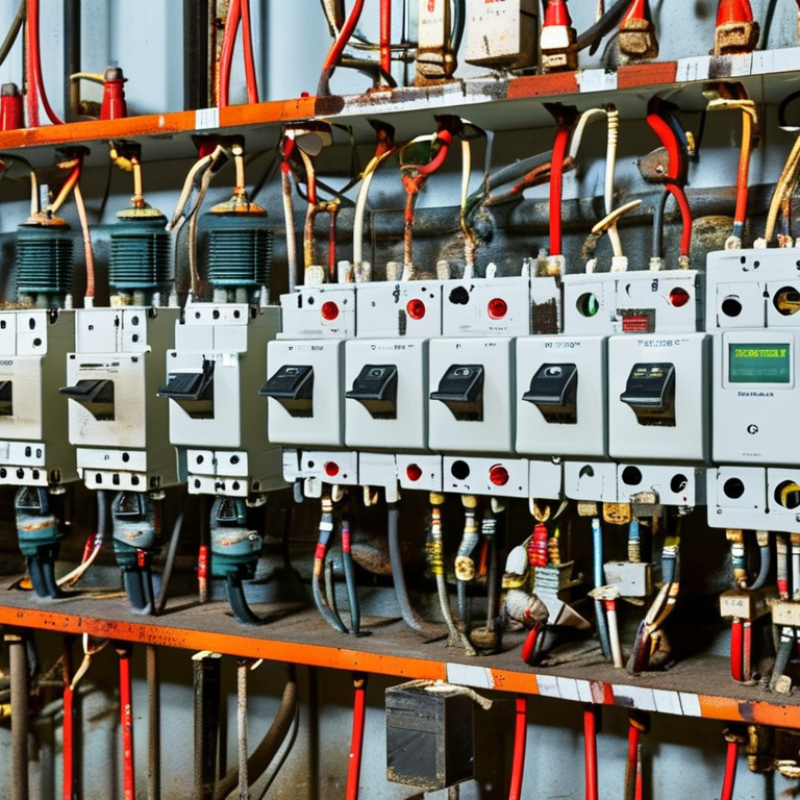
Under IEC 60947-2, air circuit-breakers interrupt faults through air, not oil or gas. The practical choice depends on installation duty, fault level, and coordination. An open-frame air circuit-breaker suits main incomers and bus-couplers in large low-voltage switchboards. A molded-case circuit-breaker fits outgoing feeders, motors, and compact distribution panels. Small thermal-magnetic devices may serve final circuits, but IEC 60898-1 often applies instead. That distinction is easy to miss.
Check the rated operational voltage, continuous current, insulation level, and impulse withstand voltage. Then compare the ultimate short-circuit capacity, Icu, with the prospective fault current at the installation point. Ics matters too, because it indicates service performance after interruption.
The International Energy Agency’s Electricity 2024 report expects global electricity demand to grow by about 3.4% annually through 2026. More load does not automatically require a larger breaker. It requires better discrimination, heat assessment, and verified cable protection. A 1,600 A frame may still fail its duty if the short-circuit study is weak.
Field experience shows another problem: designers sometimes select ratings from normal load only. That approach is incomplete.
Consider ambient temperature, altitude, enclosure ventilation, inrush current, maintenance access, and whether adjustable electronic protection is necessary. Always verify the final selection against the latest IEC 60947-2 edition and the manufacturer’s tested assembly data.
Match Rated Current: Common ACB Ranges from 400 A to 6,300 A
How to Choose the Right Air Breaker for Your Needs?
Selecting an air circuit breaker begins with rated current, not appearance. Common ACB ratings range from 400 A to 6,300 A, including 630, 800, 1,000, 1,250, 1,600, 2,000, 2,500, 3,200, 4,000, and 5,000 A. Calculate the maximum continuous load first. For a three-phase system, use I = P ÷ (√3 × V × power factor).
A 2 MW load at 400 V and 0.9 power factor requires about 3,208 A. A 3,200 A breaker may be too close. The next rating could provide safer operating margin.
Do not select by current alone. Check ambient temperature, enclosure ventilation, altitude, cable capacity, and expected load growth. The International Energy Agency’s Electricity 2024 report forecasts global electricity demand growth averaging 3.2% annually from 2024 to 2026. That trend makes future capacity worth examining. Still, oversizing can reduce protection quality. The trip-unit setting must protect the conductors, not simply match the breaker frame.
Short-circuit performance matters equally. Under IEC 60947-2, verify the breaker’s rated short-circuit breaking capacity against the installation’s prospective fault current. Review selectivity with downstream devices, especially in motor-heavy panels. In field assessments, engineers often find acceptable load calculations but poor coordination settings. I still recheck the first estimate. Site measurements, thermal scans, and updated single-line diagrams can reveal assumptions that paper calculations miss.
Verify System Voltage, Frequency, and the 690 V Maximum Rating
Choosing the right air breaker starts with three nameplate checks: system voltage, frequency, and the breaker’s maximum rating. The 690 V value is a ceiling, not a target. If a distribution system operates at 400 V, a breaker rated for 690 V may be suitable, but only after current and fault levels are verified.
IEC 60947-2 requires low-voltage circuit breakers to state key performance ratings, including rated operational voltage and short-circuit capability. Frequency also matters. A 50 Hz breaker should not be assumed suitable for a 60 Hz installation without checking the manufacturer’s technical data. Small differences can affect tripping behavior, temperature rise, and coordination. It is easy to overlook this during replacement work.
The International Energy Agency’s Electricity 2024 report projects global electricity demand to grow by an average of 3.4% annually through 2026. More demand means more upgrades, but higher capacity does not automatically mean better protection. Compare the measured system voltage with the breaker’s Ue rating, then confirm the supply frequency and prospective short-circuit current. Keep operating margins realistic. Sometimes the first selection is too optimistic. A site survey, thermal review, and protection study can expose that mistake before installation. Sources: IEC 60947-2, Low-voltage switchgear and controlgear; International Energy Agency, Electricity 2024.
Compare Icu and Ics Short-Circuit Ratings for Available Fault Current
Selecting an air breaker starts with the available fault current at its installation point.
IEC 60947-2 defines Icu as the ultimate short-circuit breaking capacity. It shows whether the breaker can interrupt a severe fault safely. Ics is the service short-circuit capacity. It indicates whether the breaker can interrupt the fault and remain usable afterward.
Check the numbers at the actual operating voltage. A breaker rated 50 kA at 400 V may have a lower rating at 690 V. IEC 60947-2 permits Ics values of 25%, 50%, 75%, or 100% of Icu, depending on the product and test category.
For example, a panel with 35 kA available fault current needs an Icu above 35 kA. If its Ics is only 12.5 kA, repeated faults may cause greater damage or require replacement. That choice is weak for a critical feeder.
Do not rely only on the largest Icu figure. NFPA 70, 2023 Edition, Section 110.9, requires interrupting ratings to match or exceed available fault current. Request a short-circuit study using transformer impedance, cable length, motor contribution, and utility data.
A field check may reveal changed transformers or added generators. I have seen selections based on outdated drawings. That assumption can fail. Also verify selective coordination, withstand ratings, and maintenance procedures before approval.
Select Poles, Trip Functions, and Protection Settings for Load Requirements
Choosing the right air breaker starts with the load, not the cabinet size. Count the live conductors and decide whether the neutral also needs switching. A single-pole breaker suits a simple single-phase branch circuit. Two-pole devices serve split-phase loads, while three- or four-pole breakers fit three-phase systems. A four-pole option can disconnect the neutral, but this choice requires careful system assessment.
Trip functions must reflect real operating conditions. Long-time protection handles sustained overloads. Short-time and instantaneous trips respond to high fault currents. Ground-fault protection may be necessary where leakage could endanger people or equipment. Check the load’s normal current, starting surge, conductor rating, and available fault current. Protection settings should remain below the safe cable limit, while allowing motors and transformers to start without nuisance tripping. I once saw a setting chosen from running current alone. It looked reasonable, but the motor stalled during startup.
Tips: Record actual load measurements when possible. Compare them with design calculations. Leave adjustment room for future expansion. Coordinate upstream and downstream breakers so the closest device trips first. Verify settings after installation. A printed label can prevent mistakes, though labels are not a substitute for testing. Have a qualified professional review unusual neutral arrangements, generator supplies, and high-energy systems. Local electrical rules still matter.

